Level Sensor Details
Site Summary component > Sensor Status button > Further Details button (bottom left of screen)
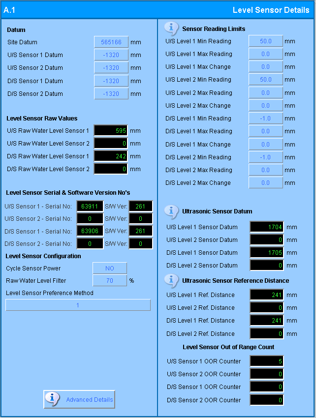
This component displays water level sensor configuration details

Level Sensor Details screen
Note
In this document, details are given for the upstream sensor 1 tags only. The other upstream and downstream tags behave in the same way unless otherwise noted.
Datum
The elevations of water and gate tip at a site are measured against some known elevation called a datum. This section gives the location of reference datum levels for the site. See Datum Levels for more details.
| Field | Description | Tag |
|---|---|---|
| Site Datum |
Distance of the Site Datum from the reference datum. Usually 10 m in a Local reference system. |
SITE_DATUM |
| Sensor Datum |
For each sensor this give the distance of the level sensor datum from the site datum. |
eg. USL1_DATUM |
Level Sensor Raw Values
The tags in this section display level sensor raw measurements as measured directly from the level sensors without using the reference elevation datum.
| Field | Description | Tag |
|---|---|---|
|
Raw Water Level Sensor |
Level sensor raw measurement (relative to the U/S level sensor 1 datum) |
eg. USL1_RAW |
Level Sensor Serial and Software Version Nos
| Field | Description | Tag |
|---|---|---|
|
Sensor Serial No |
Level sensor serial number |
eg USL1_SERIAL_NO |
|
Sensor S/W Ver |
Level sensor controller software version |
eg USL1_SENS_VER |
Level Sensor Configuration
| Field | Description | Tag |
|---|---|---|
|
Cycle Sensor Power |
Power the level sensors off and on. This is sometimes used in troubleshooting sensor faults. |
CYCLE_SENS_PWR |
| Raw Water Level Filter |
The filtering option is generally only used with level sensors that do not have a filter built-in. The raw level water filter smoothes the water level readings by removing spikes and waves. The filter value specifies the percent weight to place on the previous reading when adjusting the current reading. The default value is 70%. |
LEV_FILTER_PERCENT |
| Level Sensor Preference Method | The software supports 5 level sensor readings. Primary sensors (USL/DSL), secondary sensors (USL/DSL) and a remote sensor (remote USL). When both primary and secondary sensors are available, the reading are averaged. Sometimes, a sensor may be redeployed in a location for monitoring a level nearby which has no relation to the gate control. In this instance, the LEV_SENS_PREF may be used to block the use of this sensor for gate control. | LEV_SENS_PREF |
Sensor Reading Limits
| Field | Description | Tag |
|---|---|---|
|
Level Min Reading |
Level sensor minimum allowed raw water level sensor readings.
|
eg.USL1_MIN_READING |
| Level Max Reading |
level sensor maximum valid raw water level sensor readings. The default is zero . |
eg.USL1_MAX_READING |
| Level Max Change |
The default value for MAX_READING is 0mm. The default value of MAX_CHANGE is 0 which disables the maximum change function. When MAX_CHANGE > 0, we perform a check against the previous raw value to the current raw value. If the difference between the readings is greater than MAX_CHANGE, we assume the reading is invalid but move the previous readings closer to the current reading every minute. |
eg.USL1_MAX_CHANGE |
Ultrasonic Sensor Datum
The tags in this section display the datums of the ultrasonic sensors. When ultrasonic sensors are installed, the measurements from these sensors are checked to ensure that they do not exceed the maximum reading possible, which is determined by calculating the measurement span of the ultrasonic sensor. This span is calculated as:
ultrasonic sensor datum - ultrasonic sensor reference distance - 50mm
| Field | Description | Tag |
|---|---|---|
|
Level Sensor Datum |
Internal level datum of this sensor |
eg. USL1_USONIC_DATUM |
Ultrasonic Sensor Reference Distance
| Field | Description | Tag |
|---|---|---|
|
Level Ref Distance |
Distance from the site datum to the reference mark inside the level sensor housing. This is used for self-calibration of the sensors. |
eg. USL1_USONIC_REFD |
Sensor Out of Range Count
| Field | Description | Tag |
|---|---|---|
|
Sensor OOR Counter |
Count of how many times upstream level sensor 1 recorded a value that was out of range. |
eg. USL1_SENS_OOR_COUNT |