Local Control Tuning
Site Summary component > Local Ctrl Tuning button
Local Control Tuning Parameters apply to control objectives for conditions close to the gate, such as constant flow and constant level. The parameters displayed depend on they type of site and may include:
- Controller parameters
- Drown controller configuration settings
- Maximum and minimum gate travel limits when the gate is under automatic control
Do not change these parameters unless you have a sound understanding of control principles, open channel hydraulics and the Rubicon control software.

FlumeGate Local Control Tuning screen
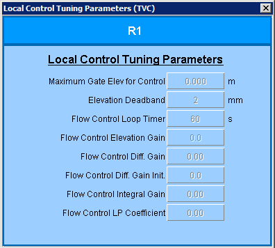
SlipMeter Local Control Tuning screen
The following fields are typically found on FlumeGate screens and on some SlipMeter screens:
| Field | Description | Tag |
|---|---|---|
| Level Control Gain | This setpoint is a parameter of the Level Controller. It is determined by a control engineer based on the dynamics of the pool to be controlled, the instrumentation constraints and the performance requirements. These tags are only used only when a site is in a Constant Upstream or Constant Downstream control mode. | LEV_CTRL_GAIN |
| Level Control Pole | A parameter used in level controller calculations in level control modes. | LEV_CTRL_POLE |
| Level Control Zero | A parameter used in level controller calculations in level control modes. | LEV_CTRL_ZERO |
| Level Control Loop Timer | Specifies how often the level controller calculation is executed. | LEV_CTRL_LOOP |
| Flow Control Loop Timer |
Specifies how often the flow controller calculation is executed. It is used only when a site’s control objective is Constant Flow. |
FLOW_CTRL_LOOP |
| Drowned Gate Controller Head |
Specifies a minimum difference between the upstream and downstream water levels (the head). The drown controller attempts to ensure that the head does not fall below this value. This minimum head tag is also the threshold for the drown alarm status on the site summary component. |
DROWN_MIN |
| ZeroFlow SP Use Max Elev Ctrl |
Specifies whether the Maximum Gate Elev For Control limit is enforced when the gate is in level control and the flow setpoint is zero. If this is set to OFF (the default), the gate will close to 50 mm above the current water level if the flow setpoint is zero and the gate is in level control. If it is ON, the gate will not close any further than the Maximum Gate Elev For Control whatever the flow setpoint. |
ZERFLOWSP_USE_MAX_ELEV_CTRL
|
| Maximum Gate Elev For Control | Specifies the maximum elevation to which the gate is allowed to travel when it is in U/S, D/S, Flow, or network control mode. It is typically used to ensure that a gate does not close above a certain elevation. | MAX_ELEV_CTRL |
| Minimum Gate Elev For Control | Specifies the minimum elevation to which the gate is allowed to travel when in U/S, D/S, Flow, or a network control mode. | MIN_ELEV_CTRL |
| Drown Alarm Timeout | Specifies how long a drowned condition must persist before the drown alarm is raised. | DROWN_ALARM_TIMEOUT |
| Drown Controller Status |
Specifies whether the drown controller will be used when the gate is in a drowned condition. The gate is considered drowned when the difference between the upstream and downstream water levels (the head) falls below a lower limit set by the Drowned Gate Controller Head. The drown controller attempts to resolve the drown condition by temporarily controlling the gate position to prevent it from opening any further until the head reaches a value of: Minimum head + Drown Avoidance Band |
DROWN_CTRL_ENABLE |
| Drown Controller in Operation | Specifies whether the drown controller is currently operating. | DROWN_CTRL_ACTIVE_STATUS |
| Drowned Gate Controller Gain |
|
|
| Drown Avoidance Band |
If the drown controller has been activated, it will not allow the gate to open any further until the head loss exceeds the value: Minimum head + Drown Avoidance Band |
DROWN_AVOIDANCE_BAND |
| Drowned Gate Controller Step | (Obsolete - only available in RTU software versions before 3.973) Amount by which the drown controller can move the gate in a single step. | DROWN_ADJUST |
| Drowned Gate Controller Timer | (Obsolete - only available in RTU software versions before 3.973) Specifies how often the drown controller calculation is executed. | DROWN_LOOP |
| Relief Enable |
When the Relief Enable tag is set to Enabled at a site, the local upstream water level is continuously monitored. If the U/S water level reaches Relief U/S Activation Level, relief mode is activated and the gate will open to allow more water to pass downstream even if this violates the other control mode settings. When relief mode is activated, the following happens:
Normal control resumes when water level falls below the Relief U/S Activation Level. |
RELIEF_ENABLE |
| Relief U/S Activation Level | U/S water level above which Relief Mode is activated. If the U/S water level reaches this limit, the gate will open to allow more water to pass downstream even if this violates the other control mode settings. As water level rises above this level, the gate will open further until the water reaches the Relief U/S Level High Limit or the gate reaches the Relief Opening Max, whichever occurs first. | RELIEF_USL_LIMIT |
| Relief U/S Level High Limit | Upper limit of upstream water level that the gate will try to relieve in Relief Mode. After this level is reached, the gate will not open any further. | RELIEF_USL_HIGH_LIMIT |
| Relief Opening Max | Maximum gate opening for a site operating in Relief Mode. | RELIEF_OPENING_MAX |
| Relief Activated | Indicates whether the gate is currently operating in Relief mode. | RELIEF_ ACTIVATED |
Additional fields typically found on SlipMeter and BladeMeter screens:
| Field | Description | Tag |
|---|---|---|
|
Maximum Gate Elev For Control Maximum Valve Area for Control (BladeMeter) |
This setpoint tag determines the maximum elevation the gate is allowed to travel to when Flow mode. This tag is typically used to ensure a gate does not close above a certain elevation. | MAX_ELEV_CTRL |
|
Elevation Deadband Area Open Deadband (BladeMeter) |
Deadband tolerance for the required gate position. In FLOW mode, the gate is not moved unless the difference betweem the current position of the gate and the position setpoint exceeds this value. | ELEV_DB |
| Flow Control Loop Timer | This setpoint tag specifies how often the flow controller calculation is executed. | FLOW_CTRL_LOOP |
| Flow Control Elevation Gain | This tag determines the proportion (gain) to apply to the flow error which determines how much the gate will move by when a gate position change is required. | IRRIFLOW_ELEV_GAIN |
| Flow Control Diff Gain | Flow control gain parameter for scaling the proportional gain. | IRRIFLOW_DIFF_GAIN |
| Flow Control Diff Gain Init | Flow differential gain parameter. | IRRIFLOW_DIFF_GAIN_I |
| Flow Control Integral Gain | Flow integral gain parameter. | IRRIFLOW_INTEG_GAIN |
| Flow Control LP Coefficient | Flow low pass filter coefficient. | IRRIFLOW_LP_COEFF |