Sonaray Configuration
SlipMeter Site Summary component > FlowMeter Status > Configuration
The Sonaray Configuration screen displays some calibration, status and configuration settings related to the Sonaray Meter.
Note
Configuration settings for the Sonaray meter are password protected. The meter must be in Configuration Mode before any configuration changes can be made.
To place the meter in configuration mode:
- In the Flowmeter Status screen, click the Configuration button to open the Configuration screen
- Click the Configuration Password setter and enter the configuration password. This places the meter into Configuration mode for ten minutes.
Note
The Configuration Password setter always displays 0, not the actual password.
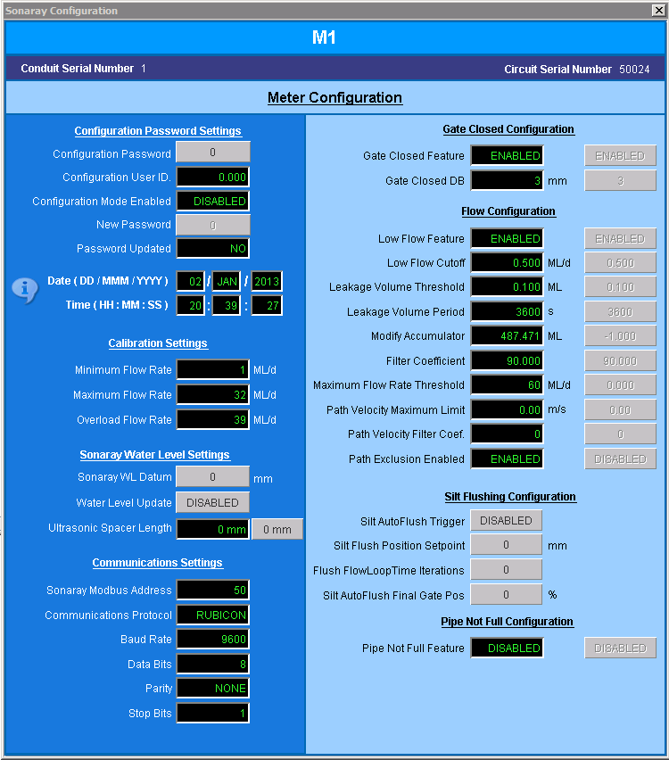
Sonaray Configuration screen
Serial Numbers
| Field | Description | Tag |
|---|---|---|
| Conduit Serial Number | Conduit serial number of the SlipMeter meter body. | ISR_CONDUIT_SERNO. |
| Circuit Serial Number | Serial number of the SlipMeter electronics. | ISR_CIRCUIT_SERNO |
Password Settings
| Field | Description | Tag |
|---|---|---|
|
Configuration Password |
Enter the configuration password to place the meter in Configuration mode for ten minutes
You can change this password in Configuration mode using the New Password setter. |
ICONFIG_PWD_SP |
|
Configuration User ID |
User ID of the user who logged in to Configuration mode. This is stored for auditing purposes. |
ICONFIG_USER_ID |
|
Configuration Mode Enabled |
Indicates whether the meter is currently in Configuration mode |
CONF_MODE_ENABLED |
|
New Password |
Set the Configuration Password. The password can only be changed in Configuration mode. |
INEW_PASSWORD_SP |
|
Password Updated |
Indicates whether the password was updated last time the meter was in Configuration mode. |
PASSWORD_UPDATED |
| Date/Time | These tags are used to display the time on the Sonaray. Use the Sync button to synchronise the time to the RTU. The hours are defined in 24 hour format. | ITIME_X where X is the time field. i.e. DAY, MONTH, YEAR, HOUR, MINUTE and SECOND. |
Calibration Settings
| Field | Description | Tag |
|---|---|---|
| Minimum Flow Rate | Minimum calibrated flow rate for the meter. | IMIN_CALIB_FLOW_Q1 |
| Maximum Flow Rate | Maximum calibrated flow rate for the meter | IMAX_CALIB_FLOW_Q2 |
| Overload Flow Rate | Overload flow rate of the meter. When the measured flow rate exceeds this value, the reading is considered to be invalid and will be ignored by the volume accumulator | IOVERLOAD_FLOW_Q4 |
Sonaray Water Level Settings
| Field | Description | Tag |
|---|---|---|
|
Sonaray W/L Datum |
Water level datum for the Sonaray water level |
SONARAY_WL_DATUM |
|
Water Level Update |
If this is enabled, the corrected water level is written to the Sonaray using the configured datum. |
ENABLE_WL_UPDATE |
|
Ultrasonic Spacer Length |
Length of the spacer tube used in the ultrasonic level sensor |
lULTRASONIC_SPACER_LENGTH_101 |
Communications Settings
| Field | Description | Tag |
|---|---|---|
|
Sonaray Modbus Address |
Sonaray local communications MODBUS device address |
ISONARAY_MDB_ADD |
|
Communications Protocol |
Communications protocol which may be either Modbus RTU or Modbus ASCII |
ICOMM_PROTOCOL |
|
Baud Rate |
Baud rate for communication between the sonaray and the RTU. Defaults to 9600 |
IBAUD_RATE |
|
Data Bits |
Number of bits used for data transmission which may be between 5 and 8 (default) |
IDATA_BITS |
|
Parity |
Specifies the parity type which may be even, odd or not used (default) |
IPARITY |
|
Stop Bits |
Number of stop bits 1 (default), 2 or 1.5 |
ISTOP_BITS |
Gate Closed Configuration
| Field | Description | Tag |
|---|---|---|
| Gate Closed Feature | Indicates whether the Gate Closed feature is enabled. If the feature is enabled, the processed flow rate is set to zero when the gate is closed and the flow accumulators are not updated |
GATE_CLOSED_CONFIG |
|
Gate Closed DB |
Gate position deadband. If the difference between the gate position and fully closed is within this threshold, the gate is considered closed. |
IGATE_CLOSED_POS |
Flow Configuration
| Field | Description | Tag |
|---|---|---|
|
Low Flow Feature |
Specifies whether the Low Flow feature is enabled. If this feature is enabled, then, when the flow is below the low flow cutoff value, the processed flow rate is set to zero and the accumulators are not updated. |
LOW_FLOW_CONFIG |
|
Low Flow Cutoff |
Flow rate where Low Flow behaviour is initiated. |
ILOW_FLOW_CUTOFF |
|
Leakage Volume Threshold |
Threshold amount of leakage permitted from a closed valve. If the leakage detected over the Leakage Volume Period exceeds this threshold, the Leakage Alarm is triggered. |
ILEAK_VOL_THRESH |
|
Leakage Volume Period |
Time in seconds over which the leakage volume is monitored. |
ILEAK_SAMP_TIME |
|
Modify Accumulator |
Current accumulator value |
IFLOW_NET_ACU_FILTER |
|
Modify Accumulator Setpoint |
Reset or adjust the volumetric accumulator values. To reset the accumulators, write a tag setpoint value of zero. To set the accumulators to another value, write the required value as the tag setpoint. The Net Volume and Forward Volume accumulator values (both raw and processed) will be set to the value entered and the Reverse Volume (both raw and processed) will be set to zero. The accumulators will then continue accumulating past this point. |
IMODIFY_ACU_SP |
|
Filter Coefficient |
A calculation coefficient used in the flow calculations. |
IFILTER_COEF |
|
Maximum Flow Rate Threshold |
Flow rate above which the MAX_FLOW_EXCEEDED alarm will be set. Set the Maximum Flow Rate Threshold to zero to disable this alarm functionality. |
IMAX_FLOW_RATE |
|
Path Velocity Maximum Limit |
Maximum expected velocity limit. Measurements above this limit are capped to this value. |
lVELOCITY_MAX |
|
Path Velocity Filter Coef. |
Coefficient used in path velocity calculations |
iVELOCITY_FILTER_COEFFICIENT |
|
Path Exclusion Enabled |
Specifies whether the Path Exclusion feature is enabled. If the feature is enabled, paths are excluded from flow calculations if they are not measuring accurately. |
PATH_EXCLUSION_EN |
Silt Flushing Configuration
| Field | Description | Tag |
|---|---|---|
|
Silt AutoFlush Trigger |
Configure the silt autoflush trigger.
Use the setpoint to set the number of silt-affected planes that will trigger a flush action, or set to DISABLED to disable silt flushing. For example, set to 2 to initiate flushing when two or more planes are blocked by silt. |
SILT_CHK_PLANE_COUNT |
|
Silt Flush Position Setpoint |
Set the gate position to use while flushing. |
SILT_FLUSH_POS_SP |
|
Flush Flow Loop Time Iterations |
Set the maximum number of flow loop timer iterations to use for flushing. Flushing will stop at the end of an iteration if it is successful in clearing the silt, or it will continue for the maximum number of iterations. |
SILT_FLUSH_N_DURATION |
|
Silt AutoFlush Final Gate Position |
Configure a position to which the gate should be set when flushing is finished but the Insufficient Paths alarm is still set. Set to 0% to close the gate Set to a positive percentage value to set the gate to a position that will pass that percentage of the desired setpoint flow. |
SILT_FINAL_GPOS_PERCENTAGE |
Pipe Not Full Configuration
| Field | Description | Tag |
|---|---|---|
|
Pipe Not Full Feature |
Specifies whether the Pipe Not Full feature is enabled. If it is enabled, then when the Pipe Not Full alarm is activated, the processed flow rate is set to zero and the processed flow accumulators are not updated. |
PIPE_NOT_FULL_CONFIG |