Level Sensor Status
Site Summary component > Sensor Status button
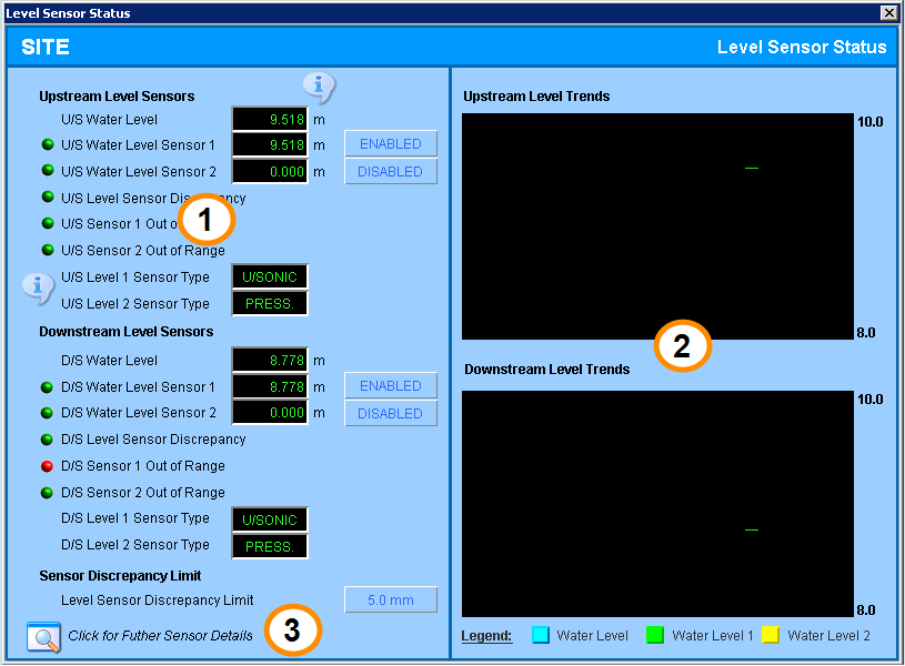
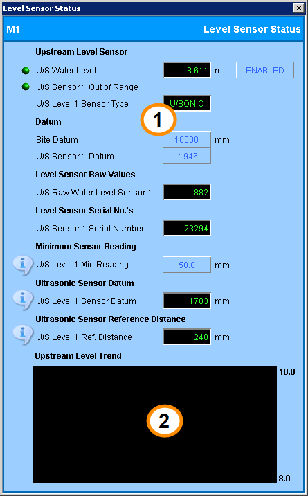
The Sensor Status screen displays water level sensor details.

FlumeGate-R Sensor Status screen

SlipMeter-M Sensor Status screen
- Sensor status settings,
- Water level trends
- Further Sensor Details button.
Level Sensor Status screen: (1) Sensor status settings, (2) Water level trends (3) Further Sensor Details button.
Sensor Status Settings
Alarm indicators are green to indicate normal opreation (OK status) and red to indicate a problem or error (FAIL status).
Details are given for the upstream sensor tags only. The downstream tags behave in the same way.
| Field | Description | Tag |
|---|---|---|
| U/S Water Level | This displays the upstream water level sensor value relative to the reference elevation datum. If there are two upstream sensors, this is the average of their values. | USL_VAL |
| U/S Water Level Sensor 1 | This displays the reading from the primary upstream water level sensor relative to the reference elevation datum. | USL_VAL_1 |
| U/S Level Sensor 1 Status |
This indicator, located next to the U/S Water Level Sensor 1 tag, shows an error in the following circumstances:
|
USL1_SENS_STATUS
|
| U/S Water Level Sensor 2 | If a secondary upstream water level sensor is installed, this displays the sensor reading relative to the reference elevation datum. | USL_VAL_2 |
| U/S Level Sensor 2 Status | This indicator displays the status of the secondary water level sensor. It behaves in the same way as the U/S Level Sensor 1 Status indicator. |
USL2_SENS_STATUS
|
| U/S Level Sensor Discrepancy |
If two upstream water level sensors are installed, this shows whether the difference between the readings from the two sensors is within the configured Level Sensor Discrepancy Limit. A discrepancy check is only performed if the check is enabled and if there are two meaningful values to compare. That is:
|
USL_SENS_ERROR
|
| U/S Sensor 1 Out of Range |
Indicates whether the measurement from the primary upstream level sensor is within range. The range check is not performed if the sensor is disabled. |
USL1_SENS_OOR |
| U/S Sensor 2 Out of Range | Indicates whether the measurement from the secondary upstream level sensor is within range. | USL2_SENS_OOR |
| U/S Level 1 Sensor Type |
Displays the type of primary water level sensor installed. The options are:
Note that when when no sensor is installed, this field will also display PRESS. To confirm that a sensor is installed, poll the sensor and check the sensor serial number. If no sensor is installed, there will be no serial number. |
USL1_SENS_TYPE |
| U/S Level 2 Sensor Type | Displays the type of secondary water level sensor installed. | USL2_SENS_TYPE |
| Level Sensor Discrepancy Limit | When dual redundant water level sensors are installed, measurements from both sensors are compared to this limit to detect measurement discrepancies. The same limit applies to both upstream and downstream level sensors. | LEV_SEN_ERROR_DB. |
Water Level Trends
The trend area displays a 24hr trend of the installed water level sensors and the calculated average if dual redundant sensors are installed.
More Details
On FlumeGate screens, click the Further Sensor Details button to display the Level Sensor Details screen.