Site Summary
Each site has a site summary screen that displays data for the site as a whole.
FlumeGate-R
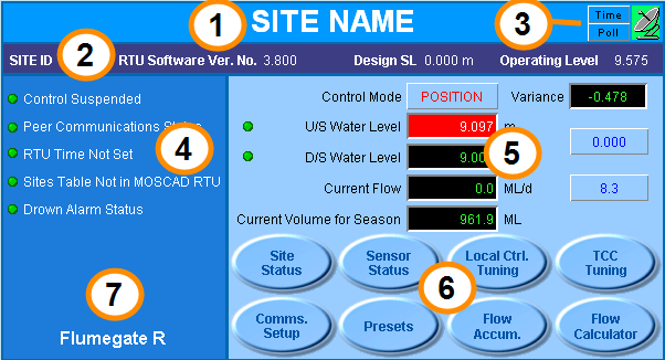
FlumeGate-R Site Summary
SlipMeter-M Site Summary
- Site name
- Site and software identification
- Communications tools and status
- Important site alarms
- Site operational data
- Access to further site details
- Type of equipment at the site
Site Name (1)
The component header displays the name of the site as configured in the database (this is the Regulator Name attribute plus the Object Name in brackets).
Site and Software Identification (2)
This area displays the following tags
| Field | Description |
|---|---|
| Site ID | This is the MDLC address of the RTU. Each RTU has a logical address (the Site ID), and a link through which it is connected (the Link ID). This allows the communications system to route communications to the RTU. |
| RTU Software Ver. No. | This is the version number of the Rubicon software loaded in the RTU which controls the gate. |
| Design SL | This is the Design Supply Level as configured in the database. The design SL is the level at which the channel is designed to be operated. |
| Operating Level | This is the operating level as configured in the database. The operating level is the level at which the channel is normally operated. |
Communications (3)
This area displays the communications related Time and Poll buttons and also displays the communications status (via an image).
| Field | Description | Tag |
|---|---|---|
|
Communications Status 
|
Shows the status of communications with the RTU
|
COMM_STATUS
|
| Time |
Click the Time button to open the Gateway/RTU Time component. This component is used to view and set the time in the MOSCAD IP Gateway and the MOSCAD RTU. 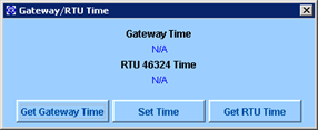
Gateway/RTU Time componentt
The clock in the RTU must be synchronised with the Gateway and with the host system for correct operation of presets. An automatic synchronisation process is configured to run every day. In most cases you will not need to update the time manually unless you don't want to wait for the automatic update (for example, after replacing the RTU). |
|
| Poll |
Click the Poll button to send a poll request to the RTU to force a poll of the table(s) within the RTU. All pollable tag values will update on the screen after a successful poll request. Note To update an individual tag, poll the tag individually rather than to use this function to minimise the communications overhead. To do this, right-click on the tag and select Poll from the list. SCADAConnect is typically configured to routinely poll all RTUs in the system to get the latest tag values, and each RTU will automatically send (burst) the latest values of configured tags if they change by a specified amount (this is configured with the change of state (COS) parameters for those tags). |
Important Site Alarms (4)
This area displays some or all of the following tags:
| Field | Description | Tag |
|---|---|---|
|
DMS Preset Comms Failures |
This tag is only relevant for meter outlets (e.g. FlumeGate-M) that have the attribute Automatic Control set to YES. This means that Rubicon’s Preset Management Service translates the water orders lodged by the customer (farmer) to preset instructions and writes these out to the outlet to operate it automatically at the lodged order times. If the Preset Management Service cannot write out the preset instruction to the meter outlet (configured to retry 3 times) this tag will be set to alert the operator of this condition. |
PS_COMM_FAILURES
|
| Control Suspended |
Control may be suspended under some conditions, meaning that the site will remain stationary in the position it was in before control suspension. Refer to the CS-OP-10 NeuroFlo User Guide for conditions which cause a control suspension for each of the control modes. |
CTRL_SUSPENDED
|
| Peer Communications Status |
This alarm only applies to sites operating under a network control strategy. To monitor the water level at the peer site, the gate operating under network control communicates with the peer site at defined intervals (typically 3 minutes). If the upstream site fails to receive a response, the tag will set to a value of 1 after retrying 3 times. Peer communications will fail if:
The tag will clear when the peer site has replied successfully. |
PEER_COMM_STATUS
|
| RTU Time Not Set | The RTU application includes a check on the RTU time. The RTU time is considered to be incorrect if the year is less than the current year as configured on the local computer. Use the Time button on the site summary screen to set correct time. |
RTU_TIME_NOT_SET
|
| Sites Table Not in MOSCAD RTU | The sites table is required for burst communications from the site and for peer to peer communications between sites. The Sites Table defines the sites in the system with which this site can communicate. The RTU application checks whether a sites table is loaded in the RTU and whether the site ID in the first row of the site table is valid. |
SITES_TBL_NOT_LOADED
|
| Drown Alarm Status |
The DROWN_ALARM tag is set to a value of 1 when it detects that the flow for any gate on site cannot be calculated due to drowned conditions. Detecting drowned conditions
These settings are displayed on the Local Control Tuning Parameters window which is accessed from the button on the site summary component. |
DROWN_ALARM
|
| Site Irrigating | This tag is only relevant for meter outlets (e.g. FlumeGate-M). It indicates whether the outlet is currently irrigating (delivering an order). The outlet is assumed to be irrigating when the gate is open by more than the Gate at Limit Deadband (GATE_AT_LIMIT_DB) or by 20mm for a FlumeGate-M). |
SITE_IRRG_STATUS
|
| Site Operating Status |
This tag is relevant for meter outlets (e.g. FlumeGate-M) that are either automatically planned, or that are manually planned but use automatic presets. It indicates whether the outlet is operating according to the ordered demand. The available states are:
If you experience false Site Operating alarms for a site type see Changing the Site Operating Alarm Wait Time . |
SITE_OPER_STATUS |
SlipMeter Alarms
SlipMeters and other devices with Sonaray flow meters may have the following fields:
| Field | Description | Tag |
|---|---|---|
| Flowmeter Comm Status | Indicates the status of the communication link status between the RTU and the SONARAY MODBUS device (flow meter). |
FM_COMM_STATUS
|
| Insufficient Paths | An insufficient paths alarm is triggered when the meter does not have enough readings available to accurately measure the flow velocity profile. This may be caused by low water levels, tampering with the meter, weeds, or silt in the pipe. | INSUFFICIENT_PATHS |
| Silt Detected | Indicates that one or more planes are obstructed by silt. | SILT_DETECTED |
| Silt Flush Status | Indicates that a silt flushing operation is currently underway. | SILT_FLUSH_STATUS |
BladeMeter Alarms
BladeMeters may have the following fields:
| Field | Description | Tag |
|---|---|---|
| Motor Board Leak | Indicates that there is a possible leak in the BladeMeter motor housing. | Gx_MB_LEAK_STATUS |
| Pipe Not Full | Indicates that the pipe is not completely submerged.The meter is designed to work in a full pipe and the computed flow is set to zero when a Pipe Not Full alarm is active for a BladeMeter. | PIPE_NOT_FULL |
Site Operational Data (5)
This area displays key site data such as the water levels, flows, volumes and also provides access to control mode changes as well as water level and flow setpoint changes.
| Field | Description | Tag |
|---|---|---|
| Control Mode |
Regulator Sites The Site Control Objective is the desired result or purpose to be achieved by all gates in Automatic Control at a site. Click this button to change the control objective. Possible control objectives are
Refer to the CS-OP-10 NeuroFlo User Guide for detailed definitions of these control modes. Note that not all of the listed control objectives may be available for the installed site/gate. |
CRTL_MODE |
| Irrigation Mode |
Meter Outlets This setpoint button displays the irrigation mode of the meter outlet. Click to open the setpoint dialog box and change the irrigation mode. The available irrigation modes are:
|
CTRL_MODE
|
| U/S Water Level | This displays the upstream water level sensor value relative to the reference elevation datum. If there are two upstream sensors, this is the average of their values. The field will change to red to indicate an alarm state. | USL_VAL |
| D/S Water Level | This displays the downstream water level sensor value relative to the reference elevation datum. If there are two downstream sensors, this is the average of their values. The field will change to red to indicate an alarm state. | DSL_VAL |
| Current Flow | This displays the total flow from the site. For a multi-gate site, this is the sum of all flows from all individual gates. | FLOW_VAL |
| Current Volume for Order | This applies to meter outlets only (e.g. FlumeGate-M) and displays the accumulated volume for an order being delivered by the outlet. | FLOW_ACC_CURR |
| Current Volume for Season | This displays the accumulated flow volume recorded on the host since the season started. This must be reset at end of season. See Flow Accumulator for details. | FLOW_ACU_TOTAL |
| U/S Sensor Summary Status |
This is a summary alarm for the upstream water level sensors. The icon is red when the alarm is set. The conditions that can set this tag are:
|
USS_STATUS
|
| D/S Sensor Summary Status | This is a summary alarm for the downstream water level sensors. The icon is red when the alarm is set.
The conditions that can set this tag are:
|
DSS_STATUS
|
| Water Level Setpoint | This is the water level setpoint which is the desired upstream or downstream water level to maintain when operating in U/S or D/S Level mode. Click this button to set a desired value. Refer to the CS-OP-10 NeuroFlo User Guide for detailed instructions. | LEV_SP |
| Flow Setpoint | This is the flow setpoint which is the desired flow rate to maintain when operating in FLOW mode. Click this button to set a desired value. Refer to the CS-OP-10 NeuroFlo User Guide for detailed instructions. | FLOW_SP |
| Variance | The variance field displays the difference between the current upstream water level and the operating level. This value is calculated by the software and is not stored in a tag. |
BladeMeter Operational Data
BladeMeters have the following additional fields:
| Field | Description | Tag |
|---|---|---|
| BladeMeter Pressure | Pressure measured at the BladeMeter. | AI1_VALUE |
| Trunk Pressure | Pressure measured immediately upstream of the junction of the main pipeline and the spur leading to the Blademeter. | AI2_VALUE |
Access to Site Details (6)
This area displays various buttons which provide access to the following screens.
| Option | Description |
|---|---|
| Site Status | Opens the Site Status screen which displays site relevant data. |
| Sensor Status | Opens theLevel Sensor Status screen which displays level sensor related data. |
|
FlowMeter Status (SlipMeter and other sites with flowmeters) |
Opens the FlowMeter Status screen which displays flowmeter configution details. |
|
Pressure Sensor Status (BladeMeter) |
Opens the Pressure Sensor Status screen which displays details of the trunk and BladeMeter pressure. |
| Local Ctrl Tuning | Opens the Local Control Tuning parameters screen which displays tuning parameters related to control based on maintaining localised objectives. |
| TCC Tuning | Opens the TCC Tuning parameters screen which allows authorised users to configure the controller parameters specific to network control. |
| Comms Setup | Opens the Communications Setup screen which displays the communication configuration details. |
| Presets | Opens the Presets screen which displays preset configuration data. |
| Flow Accumulator | Opens the Flow Accumulator screen. |
| Flow Calculator | Opens the Flow Calculator tool. |